Understanding Induced Drag – A Comprehensive Guide
What is Induced Drag?
Induced drag represents a fundamental aerodynamic force that opposes aircraft motion—an unavoidable byproduct of generating lift. This force emerges from the pressure differential between a wing’s upper and lower surfaces, the very mechanism that enables flight.
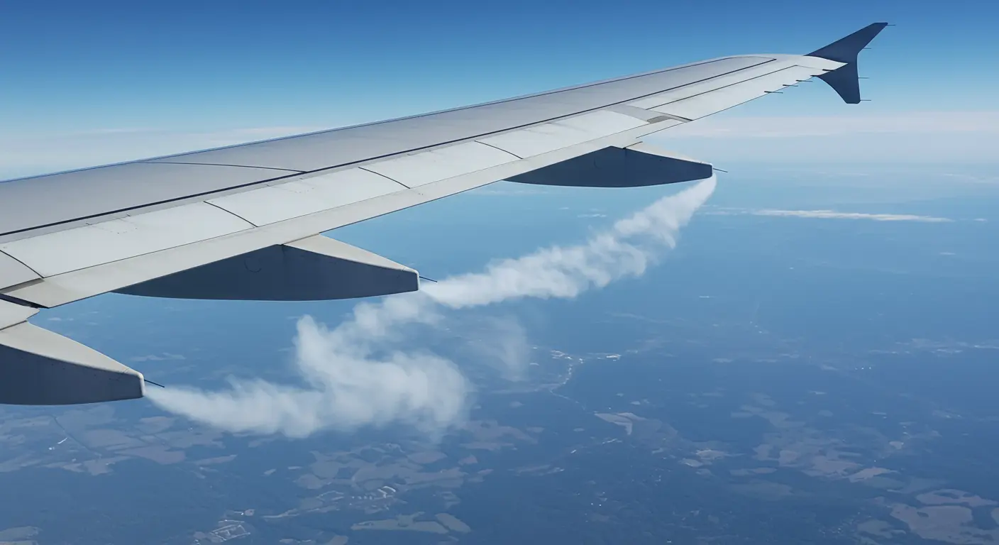
Fundamentally, induced drag stems from the backward tilt of the lift vector. Higher-pressure air beneath the wing flows around the wing tips toward the lower-pressure region above, creating trailing vortices.
From an energy perspective, induced drag represents the energy diverted into creating trailing vortices—energy that could otherwise propel the aircraft forward.
For three-dimensional wings, induced drag adds to the total drag beyond the drag experienced by two-dimensional airfoils. The spanwise flow distortion near wing tips creates energy loss, making induced drag a substantial portion of total drag. This becomes especially pronounced during low-speed, high-lift conditions like takeoff and landing.
The Role of Wing tip Vortices
Wing tip vortices are circular patterns of rotating air that spiral behind an aircraft’s wings during flight. Interestingly, these vortices actually originate slightly inboard of the actual wing tips.
Beyond performance considerations, wing tip vortices pose serious safety hazards—particularly during takeoff and landing operations. Wake turbulence from these vortices becomes especially dangerous when smaller aircraft follow larger ones.
Calculating Induced Drag
Understanding induced drag calculations is important for aircraft designers, pilots, and aerodynamics students alike. The mathematical representation shows into the factors influencing this aerodynamic force and strategies for controlling it.
The fundamental formula for induced drag (Di) incorporates several critical variables: lift force, air density, equivalent airspeed, and wingspan. Notably, the equation demonstrates that induced drag varies with the square of lift and inversely with both airspeed squared and wingspan squared.
Di = (L2) / (π × ρ × V2 × b2)
Where:
-
L is the lift force
-
ρ (rho) is the air density
-
V is the equivalent airspeed
-
b is the wingspan
For aerodynamic analysis, engineers often work with non-dimensional coefficients. The induced drag coefficient (CDI) is calculated using the formula:
CDI = (CL2) / (π × AR × e)
In this equation:
-
CL is the lift coefficient
-
AR is the aspect ratio (wingspan² / wing area)
-
e is the Oswald efficiency factor (or span efficiency factor), typically ranging from 0.7 to 0.95.
These mathematical relationships show important relationships for aircraft operations. The inverse relationship between induced drag and airspeed squared means—up to a certain point, aircraft actually require less power to fly faster.
Techniques for Reducing Induced Drag
Aircraft designers use several methods to minimize induced drag, to improve fuel efficiency and overall performance. Since induced drag varies inversely with airspeed squared, one straightforward method involves simply increasing aircraft velocity.
Wingspan modifications provide another way to reduce induced drag. Increasing wingspan directly reduces induced drag by improving aspect ratio—the relationship between wingspan and wing area.
Winglets—those vertical extensions at wing tips—represent a common yet effective drag-reduction device. By disrupting vortex formation and increasing the wing’s effective aspect ratio, they can improve fuel efficiency by up to 5% on longer flights, according to Boeing estimates.
Advanced wing design techniques further contribute to induced drag reduction. Wing taper (narrowing toward the tip) and wing twist (changing incidence angle along the span) help optimize lift distribution.
Nonplanar wing configurations offer some of the most innovative approaches to induced drag reduction. Beyond conventional winglets, designs like box wings, ring wings, and joined-wing configurations can achieve even greater efficiency by fundamentally altering how lift is generated and distributed.
Induced Drag vs. Other Types of Drag
When examining aircraft aerodynamics, understanding how induced drag differs from other drag types is important. Aircraft experience several distinct drag forms that collectively impact performance, yet each originates from different physical phenomena and behaves uniquely across flight regimes.
Two fundamental drag categories exist: parasite drag and induced drag. Parasite drag results from the aircraft’s physical interaction with airflow, encompassing all resistance that doesn’t contribute to lift generation.
Parasite drag is subdivided into three main components:
-
Form Drag: Caused by the aircraft’s shape disrupting airflow.
-
Skin Friction Drag: Results from the friction of air moving over the aircraft’s surfaces.
-
Interference Drag: Occurs where different aircraft components meet (e.g., wing-fuselage junction), disrupting airflow.
Wave drag represents another distinct category that becomes significant as aircraft approach transonic and supersonic speeds. This phenomenon occurs when shock waves form on the aircraft’s surface due to local airflow exceeding sound speed, dramatically increasing overall drag.
The practical importance of understanding these distinctions is evident when analyzing aircraft performance across different flight phases. During takeoff and landing—when speeds are low and angles of attack high—induced drag dominates, often accounting for the majority of total drag.
Ground Effect and Induced Drag
Ground effect is an interesting effect occurring when aircraft fly close to flat surfaces such as ground or water. This proximity creates significant induced drag reduction alongside increased lift efficiency.
The primary mechanism behind ground effect involves interrupting wing tip vortex formation. The ground surface obstructs full vortex development and disrupts the downwash pattern, leading to several aerodynamic benefits:
The magnitude of ground effect is related to the aircraft’s height above the ground, measured in wingspans. The effect becomes noticeable below one wingspan and intensifies as the aircraft descends. The approximate reduction in induced drag is as follows:
-
~50% reduction at 10% of wingspan height
-
~25% reduction at 25% of wingspan height
-
~10% reduction at 90% of wingspan height
The full, free-air value of induced drag returns once the aircraft climbs above a height equal to its wingspan.
This phenomenon affects for aircraft operations. During takeoff, ground effect can help aircraft become airborne at slightly lower speeds than otherwise possible, as reduced induced drag requires less thrust to overcome.
Conclusion and Summary
The relationship between induced drag and flight parameters follows predictable patterns: it increases with lift force squared, decreases with airspeed squared, and reduces with greater wingspan. This explains why induced drag becomes particularly significant during low-speed operations—takeoff and landing—while diminishing in importance during high-speed cruise.
Several proven strategies exist for reducing induced drag: winglets and other wing tip devices, increased wingspan, wing twist (washout), and wing taper to optimize lift distribution. Additionally, ground effect provides natural induced drag reduction when aircraft operate close to surfaces, with the effect intensifying as height decreases relative to wingspan.
Minimizing induced drag is important for aviation efficiency. By reducing this drag component through thoughtful design and operational practices, aircraft achieve improved fuel economy, extended range, enhanced performance, and reduced environmental impact.

